
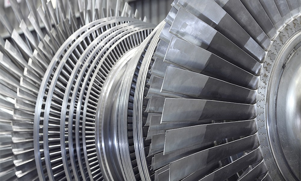
The bearing, as well as its support are made to control the dynamic and static forces. That’s why a steam turbine rotor flexes during operation.
Bending, however, can result in cascading impacts between fixed and rotating elements. An operator of numerous utility-scale steam turbines discusses their vast field expertise. Especially in determining the underlying causes of failures and effective fixes.
One of the most significant issues with power plant operations is rotor bending. This causes the blades, along with other internal parts, to break too soon. That’s when a blade blending service is required.
The issues frequently raise the cost of plant maintenance and operation. There’s a decrease in plant availability by restricting generation. Interaction between the components frequently causes extreme bending issues and failure. Let’s discuss how these can be avoided.
Align the diaphragms correctly.
Keep in mind that at typical temperatures encountered during turbine operation. The axis from the focal point of the gland’s bore should align with the shaft. Additionally, any reduction in sealing gaps during the warm-up must be promptly detected.
Due to temperature differences between the cylinder’s upper and lower parts. Changes in clearance during warming may result in bending of the cylinders.
Accurate alignment is necessary.
Be particularly mindful of the potential for tips to brush against the cylinder walls during reactive stages. Increased vibration during bending, typically near the root, can occur due to rubbing.
The shaft needs to remain centered.
In multi-casing turbines, proper alignment disappears. Especially if the longitudinal axis of a particular rotor isn’t consistent in the subsequent casing.
The separately linked drivelines must function as a single, flexible, lengthy, continuous driveline. Verify the rotor’s alignment with the couplings and any other elements. This might alter the main positions of the respective casings, bearings, and rotors. This is crucial following significant turbine maintenance – refer to https://www.mechanical-knowledge.com/2021/05/maintenance-activities-for-steam.html for further information.
Steer clear of tenon extrusion rubs.
Tube curvature also causes vibration by shifting the mass center, which changes the shaft’s rotation axis. Blades are impacted by this in important ways.
These structural issues are brought on by the vibration. Significant centrifugal forces are experienced during operation. Thus, increasing the amount of tensile force in the blade sections creates stresses. That’s if the focal point of gravity isn’t on the radius line.
Additionally, the pressure impacts of the HP steam passing axially across the cylinder. This causes the stresses in the joints. The steam flow rate, the temperature drop over the blade stage, the weight, and the rotational speed. All of these affect how much stress there is.
The mechanical characteristics and damage of the elements will be impacted by the degree of heat of the steam. This is overheated in the initial phase and submerged in the last.
Unbalance is brought on by corrosion.
External factors can cause
vibration. This includes:
- an inadequate dynamic balancing of the component
- irregularities of the diaphragm passageways
- divergence in the blade pitch
- an incorrectly assembled junction between both split diaphragms
- deterioration of the external surface of fixed blades
There may be variations in the dimensions and how they are installed. It is important to carefully preserve the same materials and weight.
This will follow a maintenance overhaul. Especially if only a few are being replaced. An imbalance as well as vibration can result from even little variations in weight or point of gravity.
Go to this website to learn more.
Inadequate maintenance can lead to failures.
Deep scrapes on the shaft resulted from the incorrect elimination of the disc. Rework and shaft rebalancing will be necessary. It is for the repair to avoid an imbalance that could result in vibration.
Bolts can be circumvented by steam.
The huge lateral joint flange in the HP cylinder is securely fastened with big bolts that are placed into the holes. A leak may develop in the bolt holes. This is a result of cylinder deformation and fluctuating duct pressures.
Steer clear of rubs.
It should go without saying that the end sealing is disrupted. This is caused by rubbing in the tunnels or diaphragms due to inadequate clearances.
Whenever the high-mass component at working speed encounters a stationary surface, this scenario frequently arises. Friction may cause a localized temperature rise at the site of contact. Thus, raising the metal’s temperature there.
A layer of metal is frequently imprinted on the surface by the forces created. That’s when the massive rotating rotor mass collides with the ineffective stationary seals. The rub may result in transient shaft bending and flexible deformation at the impact site. Vibration levels will typically rise as a result of the shaft bending.
The rotor might also come into contact with immovable parts due to uneven cooling, especially after shutdown. If left in a stationary position to cool after a unit shuts down. The comparatively high-temperature component may bend due only to the ass and gap between bearing supports. Permanent shaft bending may result from this circumstance.